
|
|
|||||||||
|
|
|||||||||
|
|
|||||||||
|
|
|||||||||
|
|
CB350 Part 3
It has been a while since I've added an update to the green CB350, and some of these pictures are pretty old. The last edition ended with disassembly of the frame in anticipation of some repairs and refinishing. The first few pictures below are documentation for reconstruction. The last picture shows the engine coming out.


The next sequence of pictures shows how to remove the frame data plate that seems to be common on most of the honda motorcycles from the early 1970s. The first picture shows the data plate in question. The second picture shows an automatic center punch that I used to put a dimple in the center of the rivet head for drilling. A regular center punch would work also, but I had one of these handy. The punch mark helps keep the drill bit centered. The idea is to drill just enough to get close to separating the head of the rivet, not to try and drill all the way through. Picture number three below sort of shows that. Once the head is weakened, it is easy to remove it by sticking the back end of the drill bit into the hole and applying a slight bending pressure to pop the head off. Picture 4 below shows the rivet heads removed. The plate is still glued to the frame, and it is made of very thin and soft metal. I applied gentle heat from a heat gun and was able to pry the plate off without any bending. You can see the results in the 5th picture below.


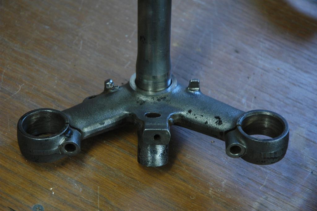
I took the steering head apart and removed the bearings, which required a special tool. It just so happens that I had a prior project (Honda Lawn Mower Clutch) that required that same tool. In that case, I just made one out of a socket and a dremel tool. If you plan to do the same, just measure the inside diameter of the desired finished teeth, then go to the cheap tool store and find a socket with that same inner diameter. It was pretty easy to grind away everything except for the four legs that fit into the steering nut. I'm not sure how the green piece got bent in the first picture. I have another set of these that are in better shape that I'll probably use on the reassembly. The second picture shows the view after I unscrewed the special steering nut.

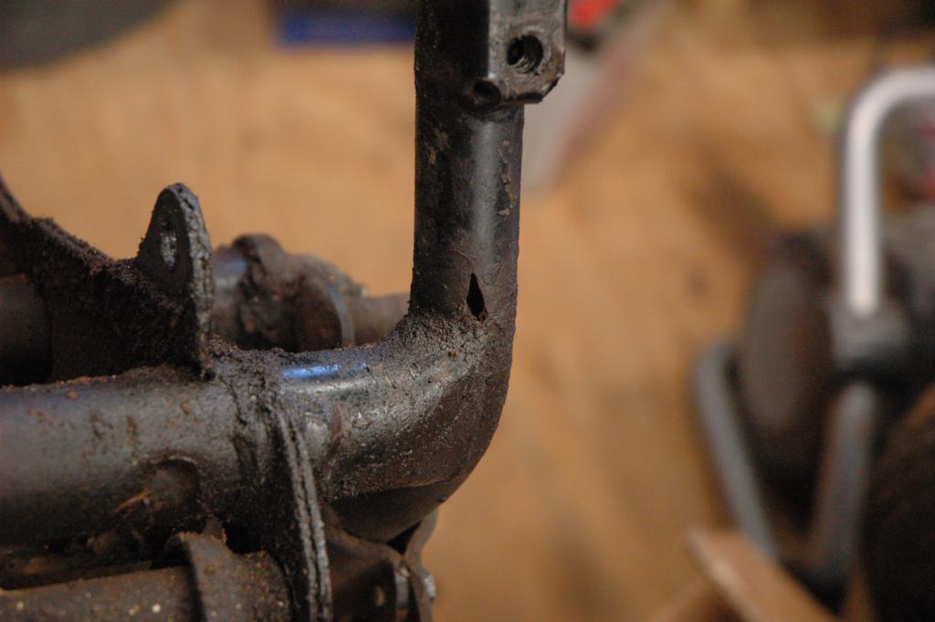
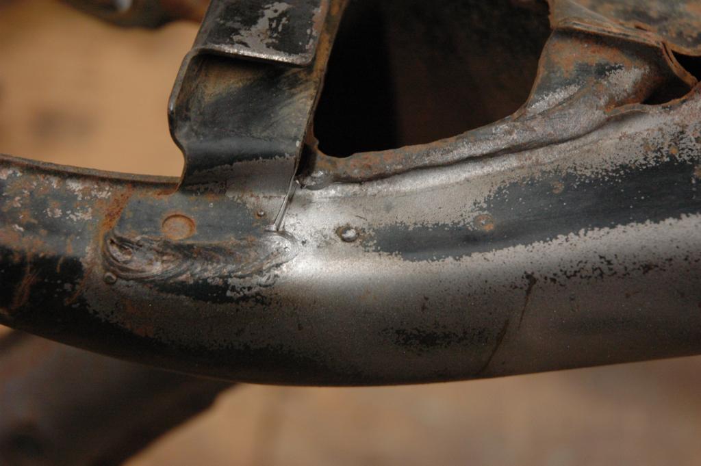
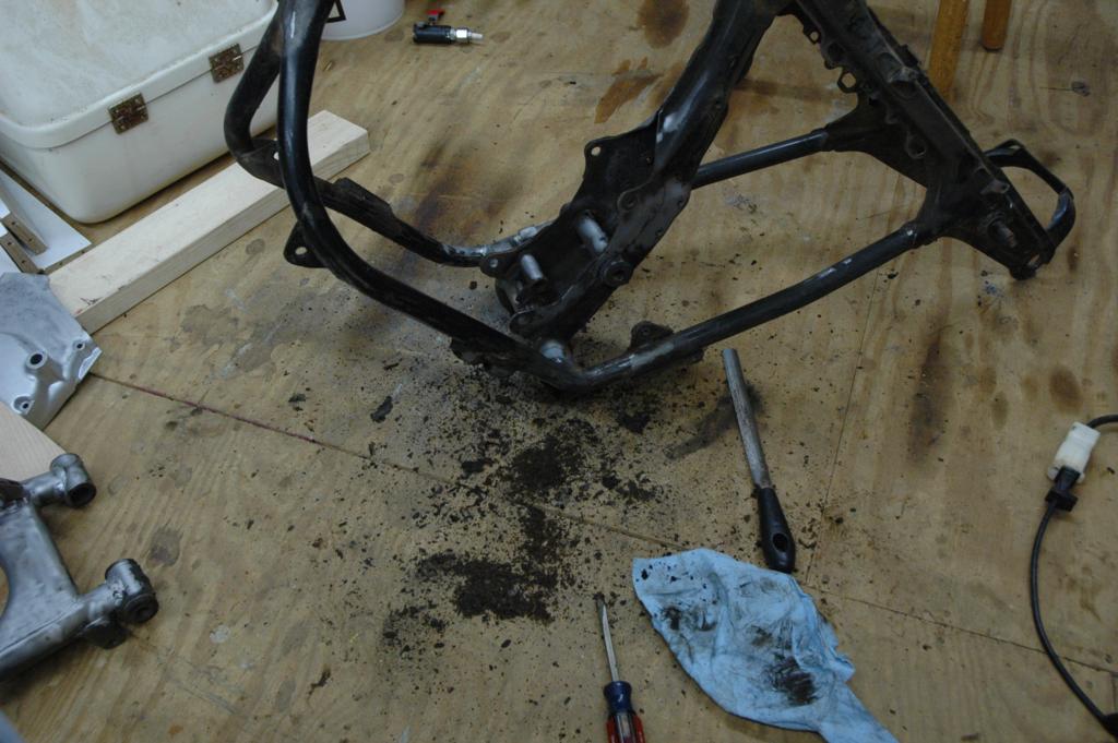
After I removed all of that stuff, I turned the frame up on end and dumped out a huge pile of rust flakes, dirt, and grass bits. You can see the results in the first picture below. The second image below shows one of the cracks in the bottom of the frame. The third picture below shows a spot on the bottom of the frame where the metal was just gone, probably from a combination of corrosion and damage. The fourth picture shows a big fat paint run on the swingarm. The funny thing is that I'm not really sure if this is the way it came from the factory, or if someone has already repainted the swingarm. I wouldn't be surprised by either- these bikes were made pretty cheaply from the start.


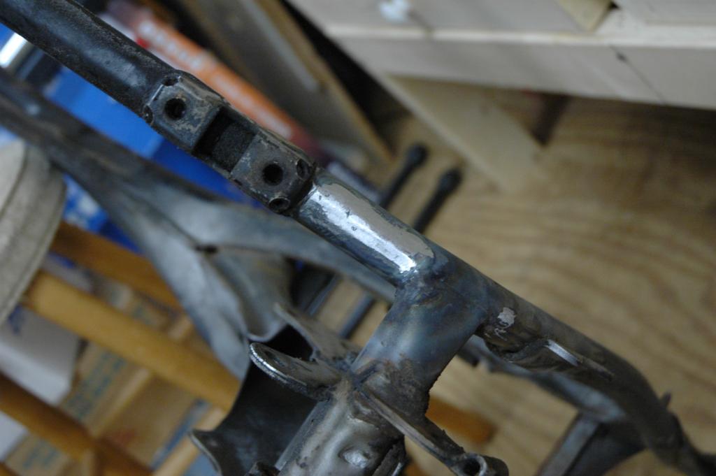
The first two pictures below are just more shots of the condition of the frame and the location of some of the damage. The second two pictures show the repair of the crack that I mentioned above. I used a sandblaster to clean the area, and then used a dremel to cut the crack area out. In retrospect, I could have just welded the crack shut and it wouldn't have been any worse. I was still learning how to weld, so it isn't perfect. The fifth picture below shows the final result after touching up. The middle pictures in the second row show a before and after view of the bonus welding rod blobs that came from the Honda factory. This is a great way to tell if the frame paint is original, and also a great example of why I don't really get caught up on the whole originality thing. If you are looking at a supposedly original honda that has a perfect frame with no weld blobs or paint problems, be suspicious. The last picture in the second row is a before and after picture of the blasting process. I used glass beads with a cheap pressure tank blaster from China. It lasted long enough to do this one project.


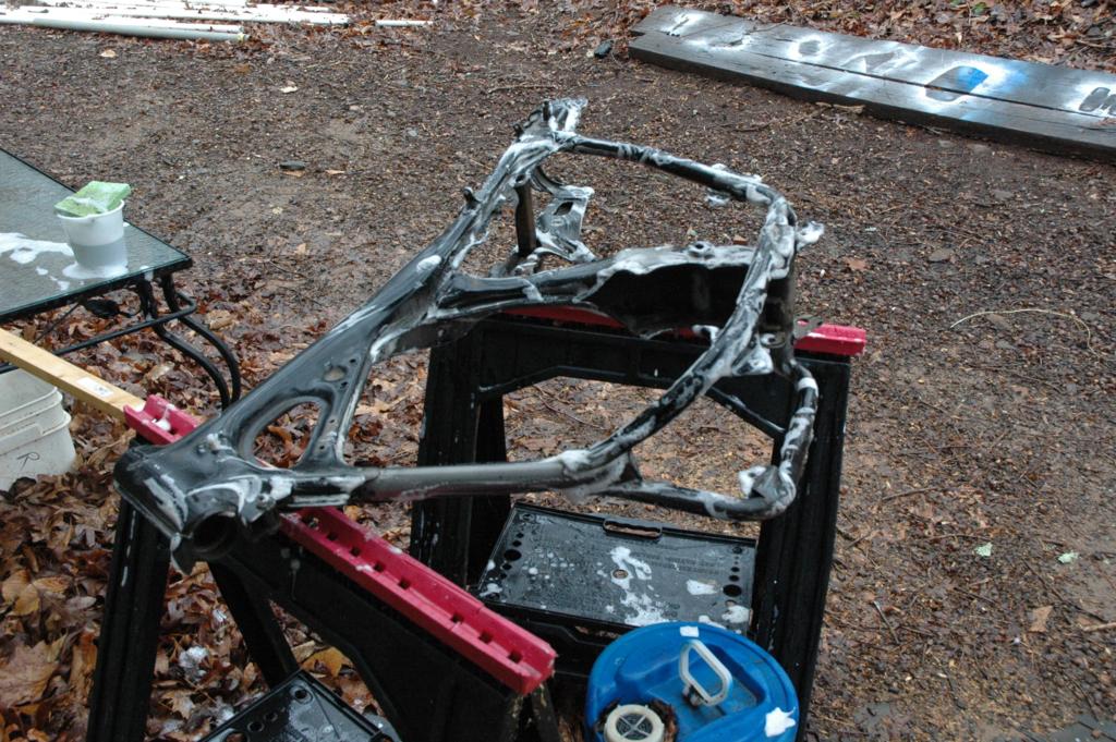
The first picture below shows more of the stuff that I dumped out of the frame. In the second picture you can see some soap sudds that were part of the scrubbing process. The third picture is of the tripple tree after electrolysis. The last picture is my make-shift blasting area. The cardboard box is there to hold a trash bag, which collects the blasting media. I reused the media from the bag after sifting it through a screen.


I wanted to have the frame powder coated for durability, so I didn't finish blasting the frame. It cost $150 to have them blast and coat the frame, so it was well worth it. There are lots of other little steel pieces associated with the frame, and I wanted to refinish those on my own. The next series of pictures show that process.


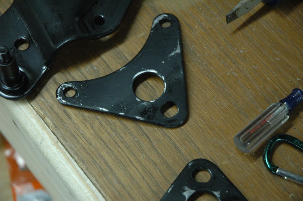
I used a spray-can epoxy frame paint that is sold with the purpose of painting motorcycle parts.


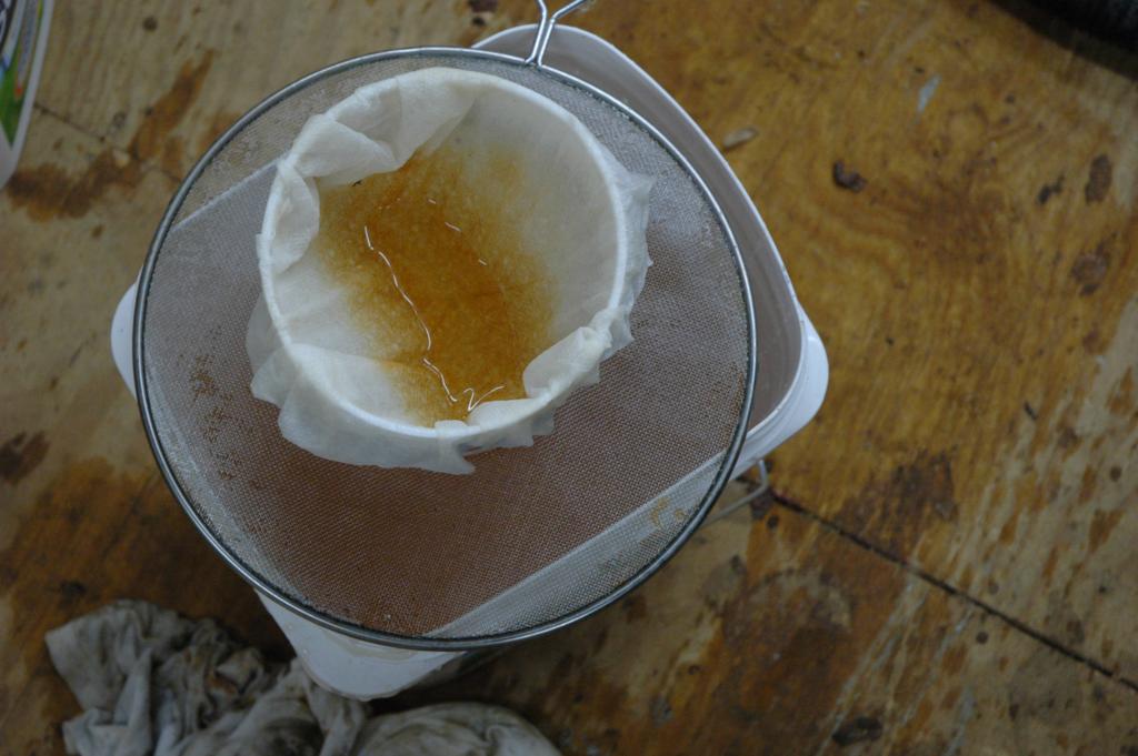
After I had a beautiful new looking tripple tree I realized that I had used the wrong one. It turns out that there is a difference between the 1972 and 1970 year models on this part. The first picture below shows the differences. The second picture shows the results of filtering the rusty water from the electrolysis process, but I'm not sure why it ended up here. The third picture is of the center stand, and it is another great example of the sloppy OEM welding. The shiny spot is one area that I've already ground. These little knobs come right off, since they aren't very thouroughly welded. The other pictures are just more pictures of the prep and paint process. I had already painted some of the pieces, but wanted to try for a smoother finish, so I sanded them with fine wet sandpaper and repainted them again.


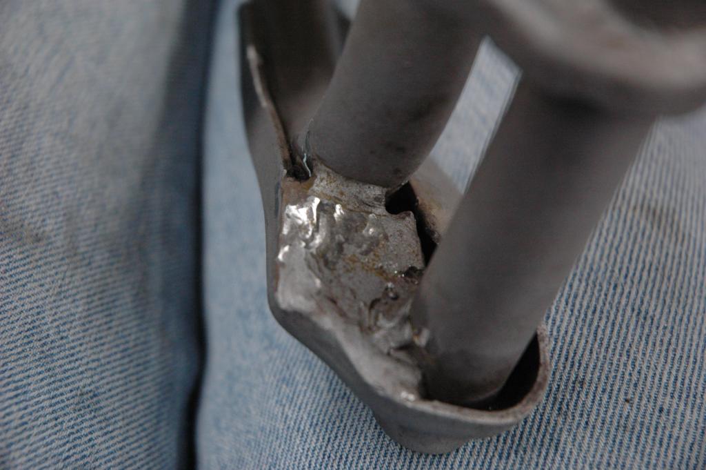


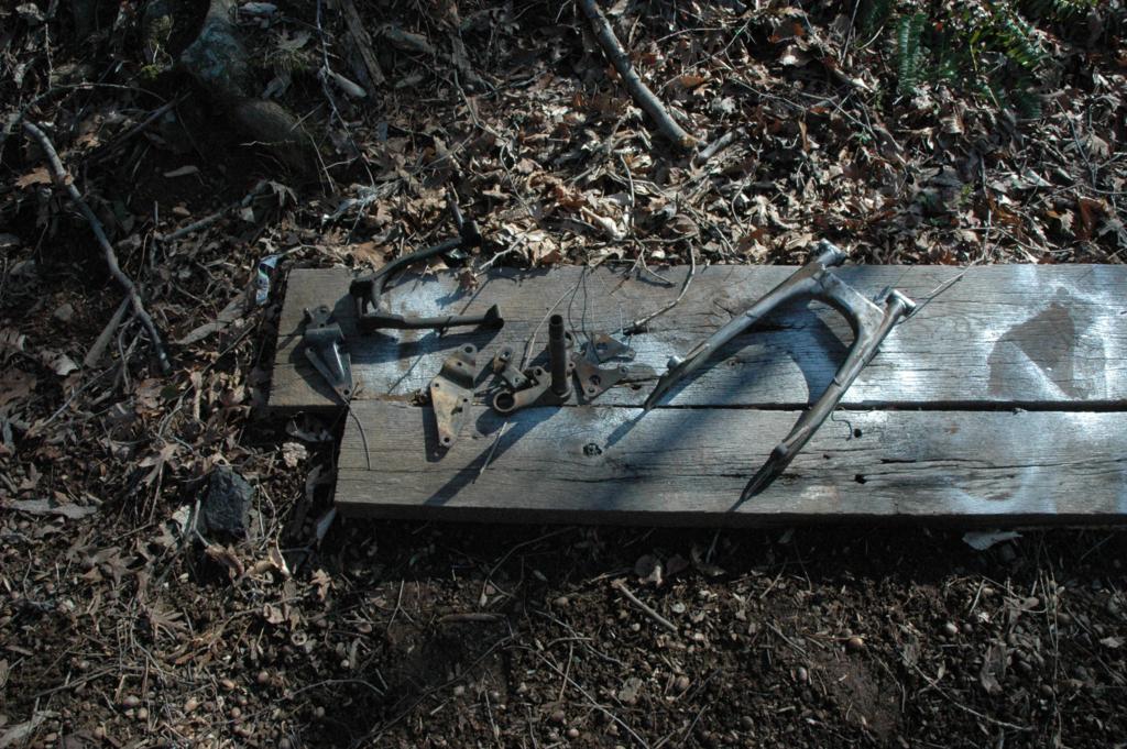
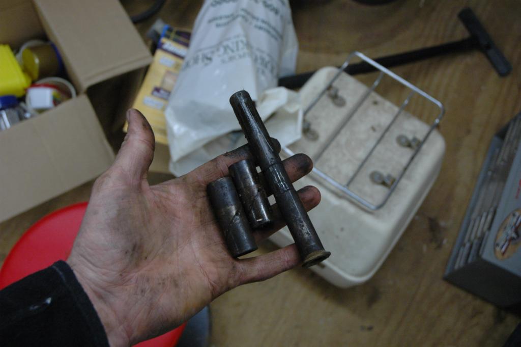
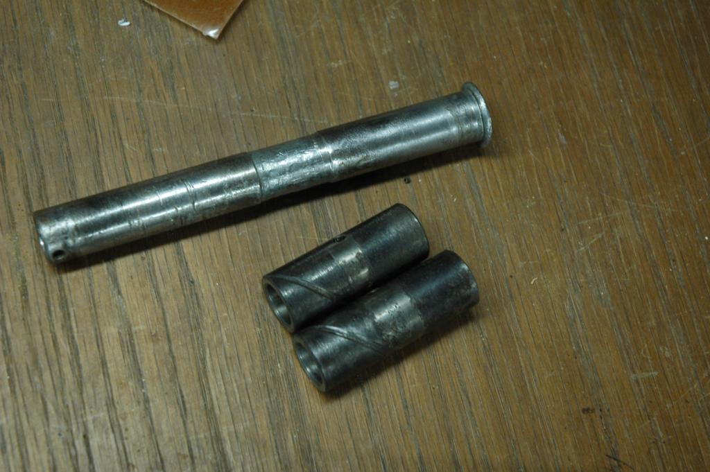
The first picture below is of the footpeg bar and the kickstand. The rest of the pictures are of the swingarm bearings. I call them bearings, but they might be more appropriately called bushings. The second picture shows them in the "as removed" nasty stage, and the others are after cleaning. The shorter tube is the attach for the center stand.


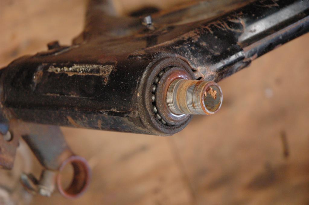
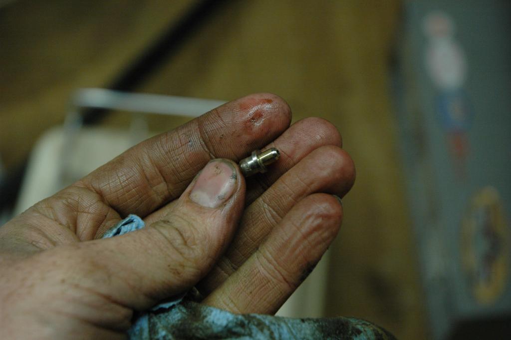
The next few pictures show the swingarm bolt. The third picture shows the progression of nasty grease out of the grease fitting.

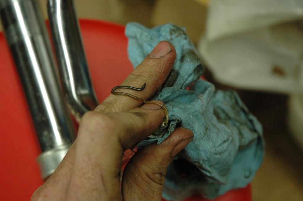
The first picture below shows the steering bearing race for a tapered bearing. I'm going to try out a set of tapered bearings and see how they work out.

I've been focussing on getting the red CB350 and the RD350 going (and building an airplane and raising the chickens and the rest of life) so I haven't made much progress on this one lately. The other day I put the top end of the engine back together, and now I need to prep a few more parts for painting. I have been working on a separate page for the engine overhaul, and once I have a few hundred miles on a rebuilt engine I'll publish that page. I'd like to make sure that I haven't done anything wrong, at least not without making it known.
| Home | Contact Me | Copyright © 2014 Jared Yates - All Rights Reserved |
|
Privacy Policy | |
| This page last modified 06/21/24 | |||||