
|
|
|||||||||
|
|
|||||||||
|
|
|||||||||
|
|
|||||||||
|
|
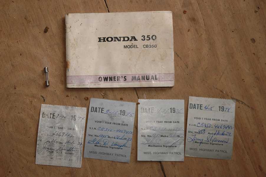
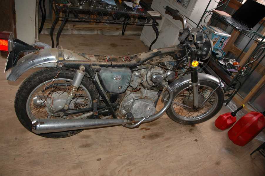
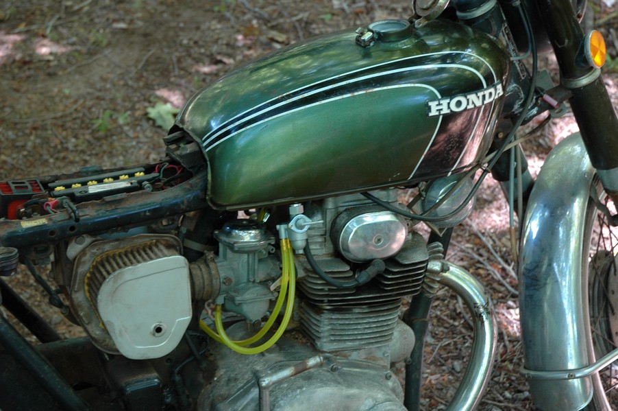
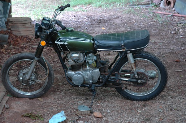
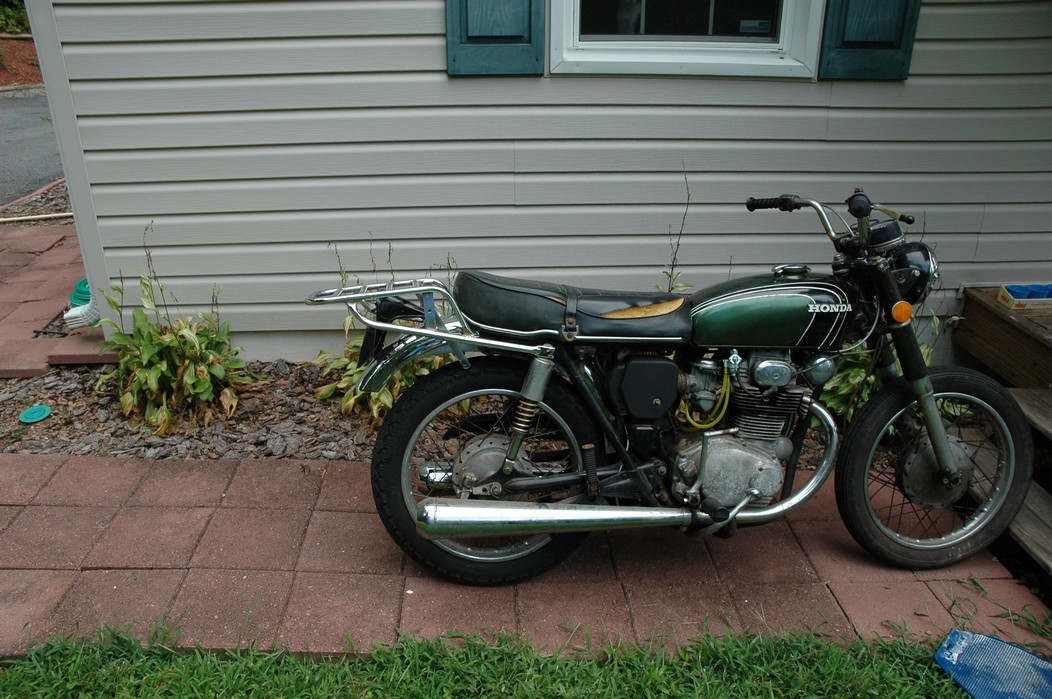
1972 Honda CB350
According to honda.com, "Honda dealers sold more than a quarter-million CB350s over the model's five-year run - 67,180 of those in 1972 alone."So here is a 1972, one of the 67180. Thanks to Mark, it's my next project. These are pictures of it that I took when I picked it up.


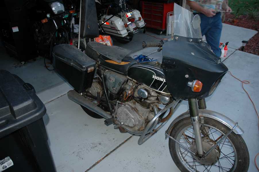


With 23390 miles, this one has seen more riding than the SL175. From what Mark says, I'll be the 3rd owner. This one is more complete than the 175 in some ways, since it does have its original owners manual and toolbox.
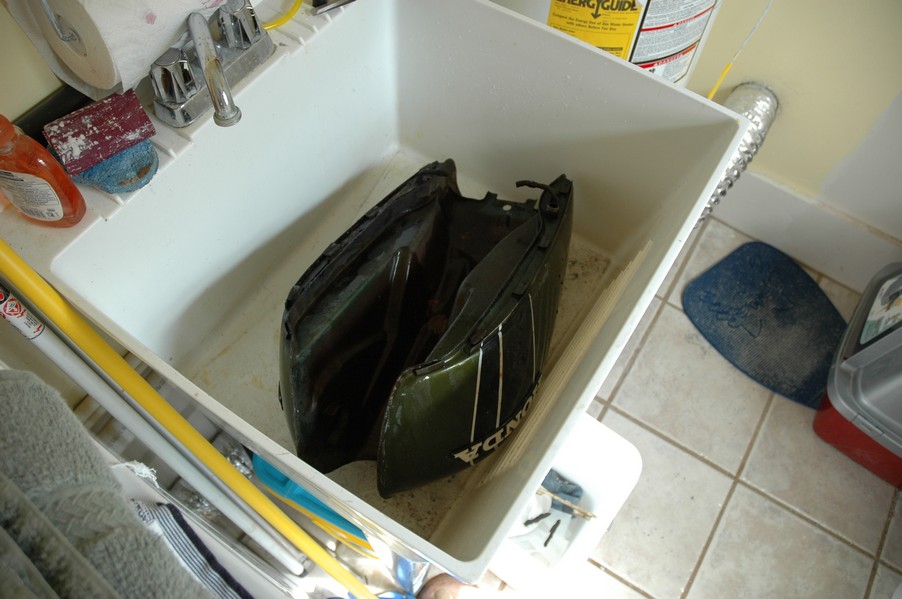
Since my SL175 has been giving me some trouble, I decided to take a break and work on the CB for a little while. I started by taking off the accessories and giving it a bath.


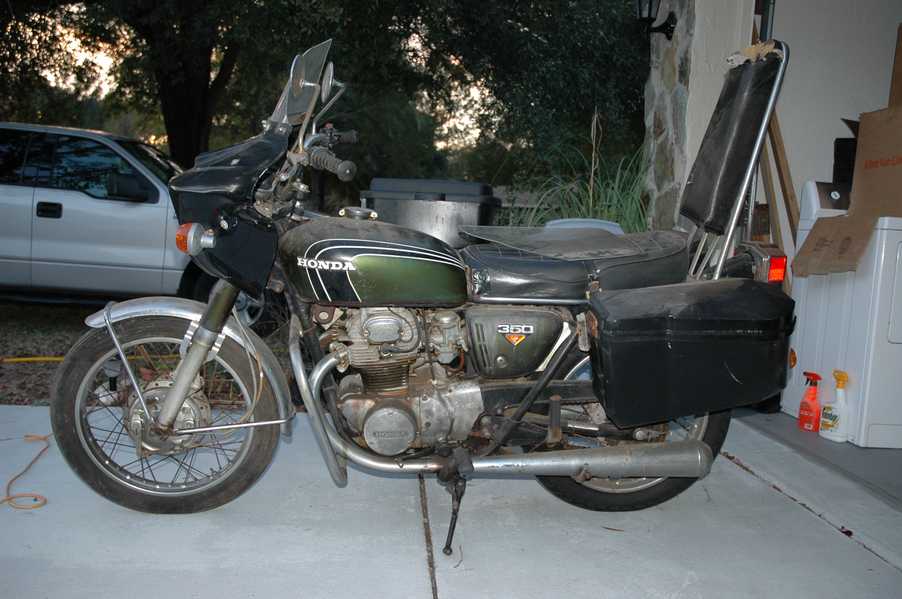
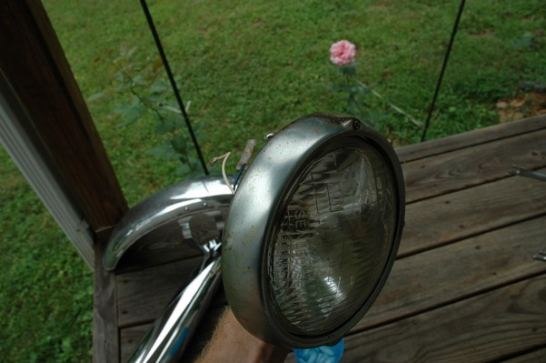
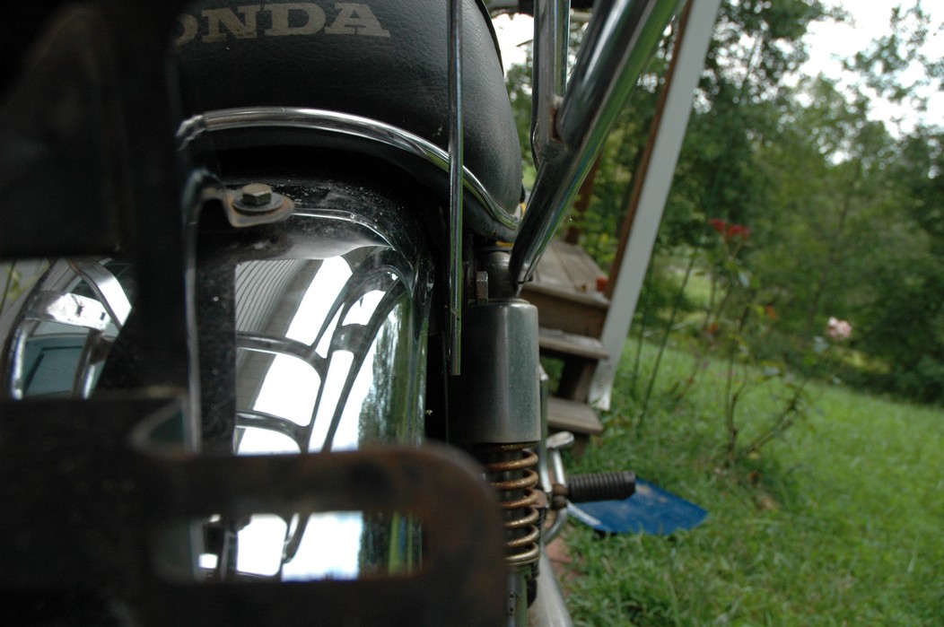
Wow, there was a motorcycle under that faring. In the pictures below you can see that the chrome front fender has some pitting, and of course I've included a picture of the ancient turn signal light bulb.


The first owner had trouble with the rectifier, so he put on this aftermarket version. Unfortunately I sheared off the stud when I was taking off the acorn nut that holds on the sissy bar and suspension. I haven't taken it apart further yet to see how complicated the repair is going to be. The aftermarket rectfier looks a little bit recti-fried, so I'm going to try to find an OEM replacement on Ebay. Or is it the voltage regulator? Hmmm... me and lots of other people seem to get the two confused.


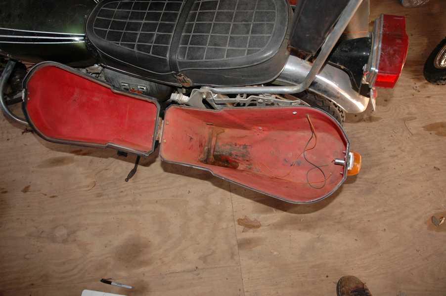
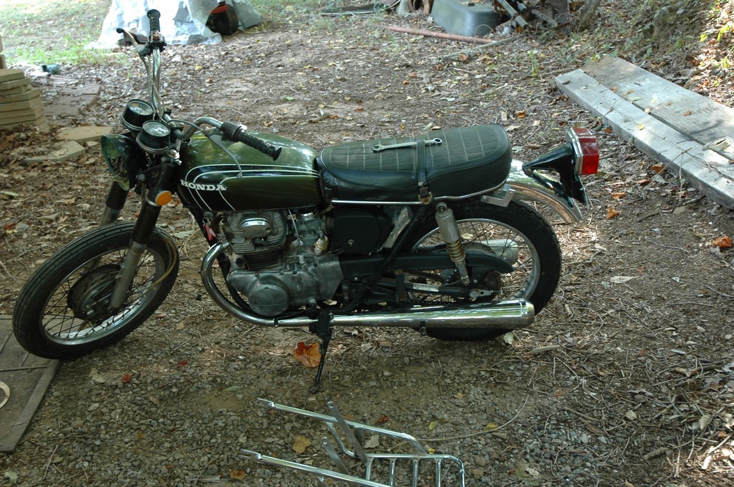
With the saddle bags off, it is really starting to look like a CB. The sissy bar isn't going to be a part of the restoration, but I have found a luggage rack to put there instead.


The seat cover is in rough shape, and so far all that I've found on ebay is a little bit expensive. I've decided to focus on getting it running first, then to worry about the seat cover in phase 2.
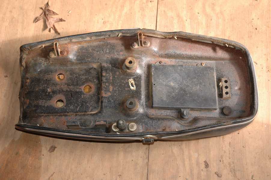


I guess the battery was a little bit short, so someone put in this 1/4" piece of aluminum and 3/4" pieces of wood to stack it up a little bit higher. Under the owner's manual you can see four Mississippi inspection stickers, ranging from 1974 to 1978.


The fuel line had reached it's service life limit some time ago, so it was actually the consistency of uncooked macaroni. If I tried to bend the line it would break off into crispy little pieces. The lever on the petcock is broken off too, which will be something good to fix in the long run.


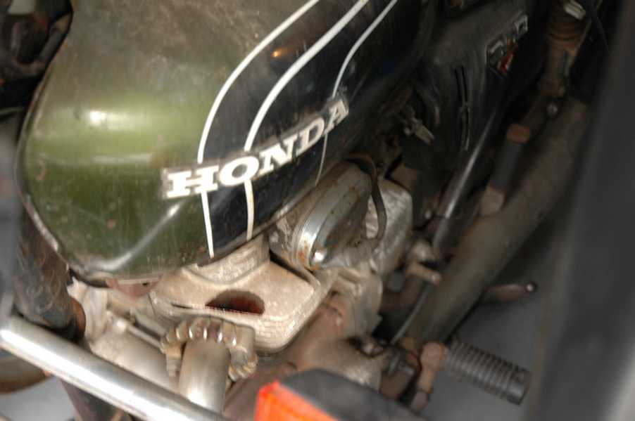
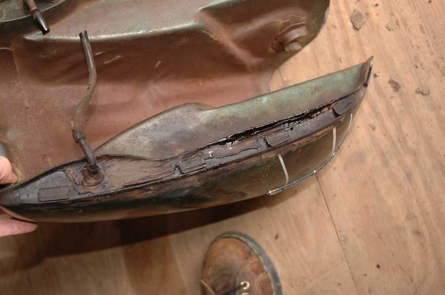
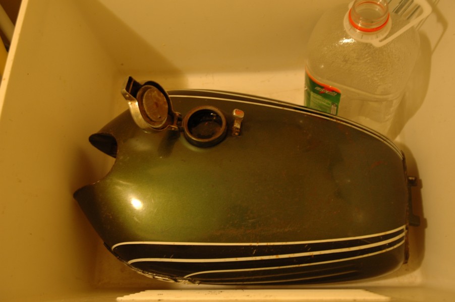
The especially astute reader might have noticed in an earlier picture the tell-tale pool of gasoline varnish on the top cooling fin of the left cylinder. This was actually coming from a leaking fuel tank. It had been repaired before, but the repair doesn't seem to be holding up too well. I'm hoping to use the Kreem products to seal the whole tank, especially since there was quite a bit of rust in the float bowls.


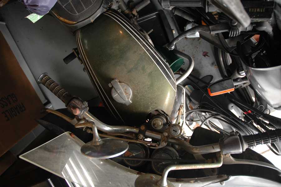
Here you can see the original ignition key mounting location, and get a good idea of how dirty the whole frame is.


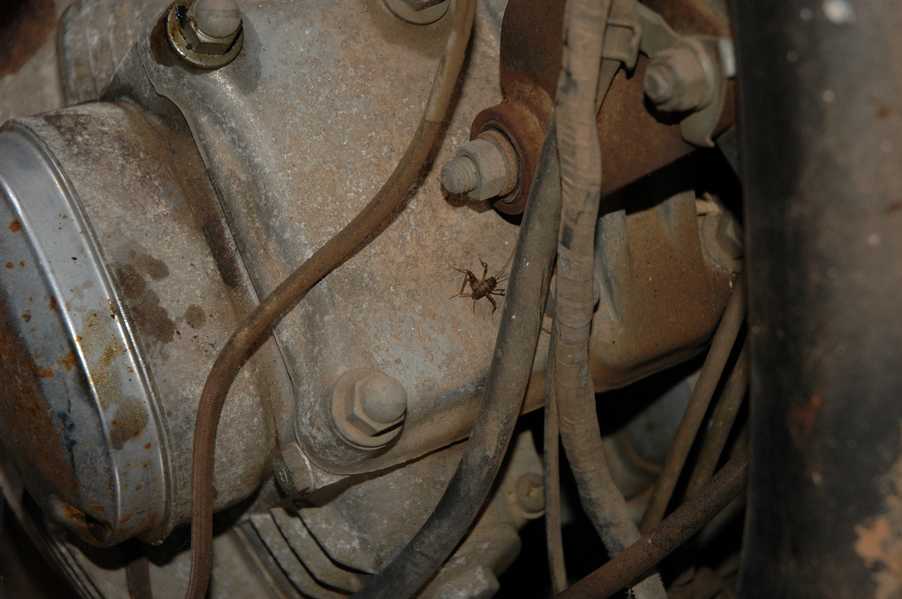
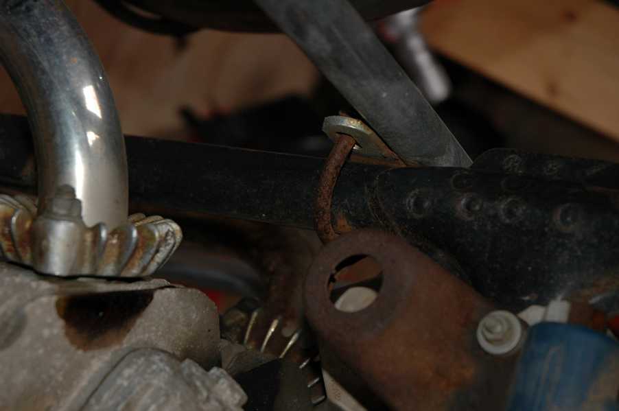
Do you see the pool of varnish yet? Look in the pictures just above. There is a little cricket who is just itching to check it out. Below you can see the wax left on the front end parts, which will hopefully come off fairly easily. The rusted u-bolt is from the crash bar. I guess it wasn't chrome plated like the bar itself was. After all of that work, the bike was ready for a nap. You can see it snoozing and also see how dirty the bottom is.


With everything off, you can really start to see some similarity between the CB and the SL175. The fenders are set up differently, and the SL has a double-downtube frame, and of course the exhaust is more like the CB175.


The petcock has definitely seen better days. One of the many amenities that the CB has over the SL is the locking seat and helmet hooks. Since they are only accessible from under the locked seat, it gives an option for leaving a helmet in a semi-secure location. The air filters were dirty as I would have imagined, though I suspect they are servicable, which is more than I can say for the powder that I found on the 175.
6-2008 Update- It doesn't appear that it is possible to clean the filters. Replacements are expensive, and hard to find.


The side covers have badly oxidized paint on the outside, and I'm hoping that they will look better after some cleaning. There is a rubber balancing tube that goes from one air cleaner to the other. In picture 3 you can see a screw head after removal by drill, and finally the crankcase vent tube (much like all to many other parts) has started reverting to its original ingredients.


When I was coasting down the hill from the trailer to the work area, I noticed that the front brake was pretty weak. The back brake was also pretty weak, though mostly because one of the vent tubes was getting in the way of the pedal's travel. In the first picture you can see the squeeze. The last two show a few little wiring problems, though nothing major.


Here is more creative wiring, along with a tank strap in pretty poor shape. The good news is that these are being reproduced and are available as new rubber. The rear fender will look a lot better after a rinse and polish, but that's for phase 2.


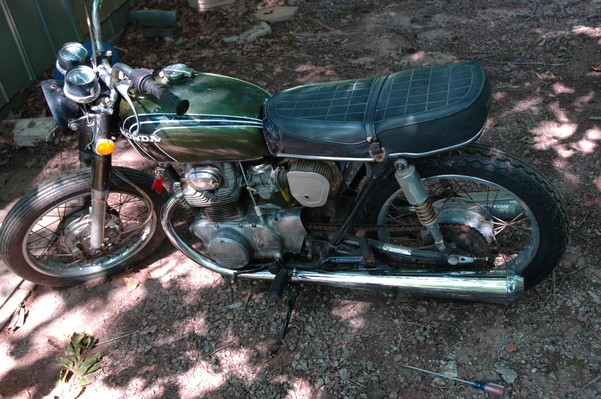
Below in the first picture you can see the worst side of the engine, though I'm not sure where it got exposed to the elements. Maybe the motorcycle was parked under a lean-to, or something like that. The OEM toolkit is in good shape considering the circumstances, though it too could use a bath. The third picture is me trying to give the CB a little motivation by showing how pretty it can be. Hopefully the SL wasn't whispering sweet "engine not runnings" into it's ears. The last photo below is the "before bath" shot.


These two are "after the bath" shots, and you can see a large difference. Photo 3 shows the degree of insect infestation in the cooling fins of the engine. The SL had the same problem. The last phot shows where the OEM turn signals will mount, along with the black headlight bucket. It will take some research to see if that is the stock color. The SL uses blue to match the tank and side covers.


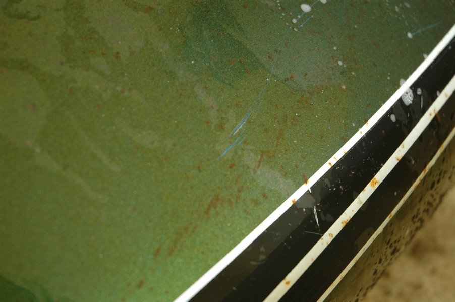
The last two pictures are especially interesting. It seems that the fork ears used to be blue- probably the same shade as my SL175. This is interesting because Mark was under the impression that the paint was original, though it probably is original on the tank and side covers. I'll be interested to see when I look over the tank a little bit more closely.
6-2008 Update: This impression seemed logical, but it was wrong. It turns out that the Honda metalic colors of this era are actually built up with layers. In the case of simple colors like blue and red, they sprayed a silver metalic coat and then followed it with a transparent tint to get the metalic candy effect. Leslie told me that in the case of the olive, they crossed blue and orange, which would explain why the blue shows up when the orange is worn through. I read in a magazine that the OEM finishing process can be a challenge even for a professional painter, which is something to keep in mind if one tries to reproduce it.


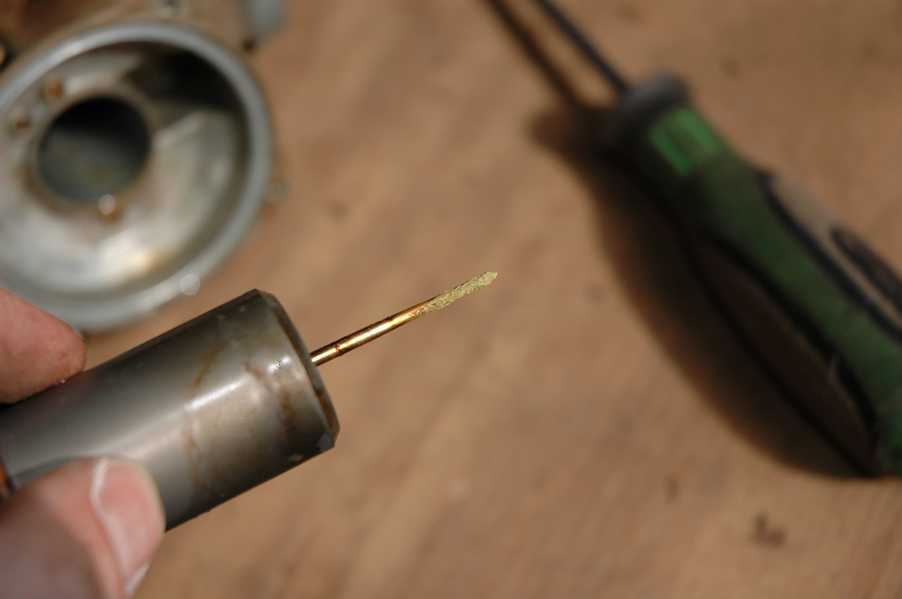
The carburetors are certainly the next logical step. These are CV carbs, so they are a little bit different than the SL's. I was glad to see that the diaphram wasn't torn, since a replacement pair runs about $80 on ebay, when you can find them. The slide needle had some interesting green crusty stuff on it, perhaps due to moisture lower in the carb.


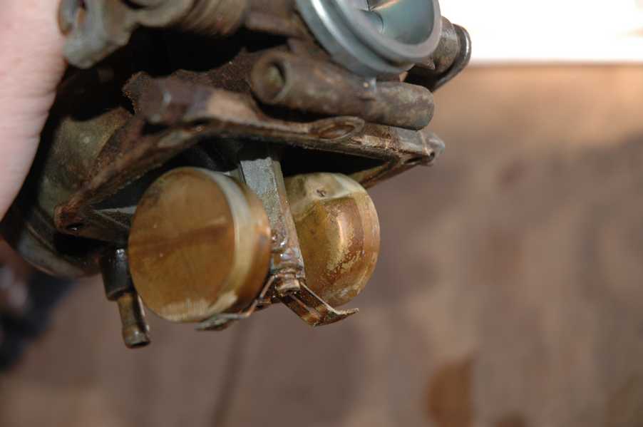
I see one thing for sure about the CV carb- it has a lot more little passages to get clogged. In the first picture below you can see all of the air passages that contribute to the slide position. The good news is that the area above the diaphram is only exposed to air, unlike the float bowl, which is mostly exposed to fuel. Picture two shows how nasty gasoline really is when it has long enough to sit and age. Picture two also shows, though somewhat subtely, how I poked a hole in the float. The last picture shows it more clearly. I was using a screwdriver to separate the float bowl (which isn't really a good idea, by the way) and when it finally did separate the screwdriver hit the float.


Picture 1 below shows the float needle soundly burried in varnish goo. I've decided to take the easy route and order new carb kits that include replacements, since I was going to have to replace the float bowl gaskets anyway. It seems silly to pay $15 for a gasket when I can pay $20 for a carb kit including a gasket and all of the jets and needles. The second and third pictures show the outside, which is what happens with the aforementioned varnish goo is allowed to collaborate with dirt. The last picture shows the float, which I tried unsuccessfully to repair. I used the same soldering technique that I used on the 175, but this one's hole was much bigger. I knew I was going to need a throttle cable, carb kits, and a few other things before I could try to run it, so I also ordered another float from the same people. The company that I used is Sirius Consolodated Inc., which has a large inventory on ebay. It was nice to find more than one part from the same seller for a change. I also found a voltage regulator on ebay and have it on hand for when the time comes.
6-2008 Update: This idea of repairing carb floats by soldering seemed like a good one, but I don't recommend it anymore. I've done it twice, and in both cases it worked well enough for a short time, but eventually led to floats full of fuel.


These last few pictures show the result of lots of scraping and scrubbing with carb cleaner spray.


Here is Carb number 2:


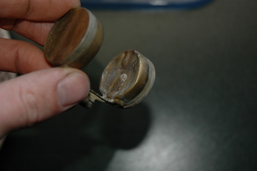
It turns out that the float in this carb was damaged, this one not by me. Since I didn't want to order another new one, I was able to combine my two broken floats into one good one. I took the left chamber off of one and combined it with the right chamber of another.
6-2008 Update: See the note above about repairing floats. This one failed too.


The oil drain plug looks like it took a hit to a curb (or two). I happened to have a spare plug for the 175, and it was the same fit. You can see the two as a before and after. The second picture is the heavily rusted original ignition mounting bracket, with the ignition switch relocated to it. The third is a picture of the new (to me) regulator that I used to replace the shady aftermarket version. The last picture is the new throttle cable from Sirrius.


The carb kit didn't include everything, but it was a good start. The last three pictures show the start of the fuel tank lining process. I used the Kreem 3-part kit.


I followed the directions exactly, though I was surprised at how long it took the etch step to work. For me it took almost 24 hours, but it looked really nice inside. I was also surprised at how much baking soda it took to neutralize the acid- about 5 boxes in all. Be sure to add them slowly, and be prepared for the science class volcano.


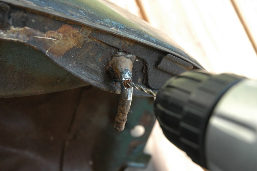
Everything went really well until it occured to me that I should check to be sure that the crossover holes weren't going to be plugged with the Kreem. One of them was fine, but the other was completely blocked with a combination of rust and fuel varnish. I would have really liked to have known that before I relined the tank, but then again I just never checked. I tried using a wood screw to clear the hole, in addition to several different types of wire and carb cleaner. I was able to get a lot of junk out of the tube, but not enough to clear it completely.

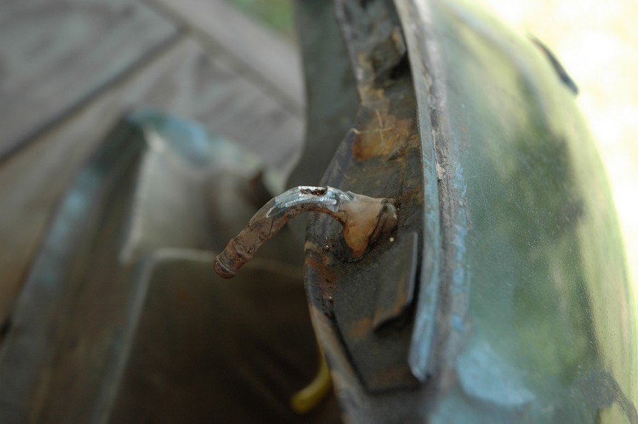


You can see the fix that I used- I ground the outer wall off with a dremel, then used a drill bit to clean out the debris. After seeing how deep it was, I'm convinced that I would have never opened it up using my other method. Then, I just slid a piece of tygon tubing over the hole, which should prevent leaks for a while. I also made a fuel cap gasket out of cork gasket material. It isn't as good as the original, but it seems to work.


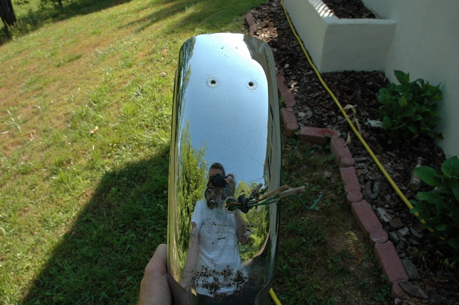
I found a new petcock on ebay for about $50, mainly because the lever was broken off of the old one. It looks nice to have the tank back on, so I decided to spend a little time with the rear fender. Like most of the chrome on this bike, the fender has lots of pitting. I washed it with a little bit of carwash soap and then polished by hand with Turtle Wax Chrome polish. I was pleased with the results. The shiny part is on the side that was accessible to previous polishers, while the hidden side is still in poor shape.


I also polished the turn signals and I painted the inside of the fender with a rust-neutralizing primer. The rust was very thick, and I'm sure it will be exposed to a high moisture environment again soon. The last picture is of the gear shift lever that I took off. I am not sure yet, but it seems like it is homemade, and even perhaps from a different brand of motorcycle.


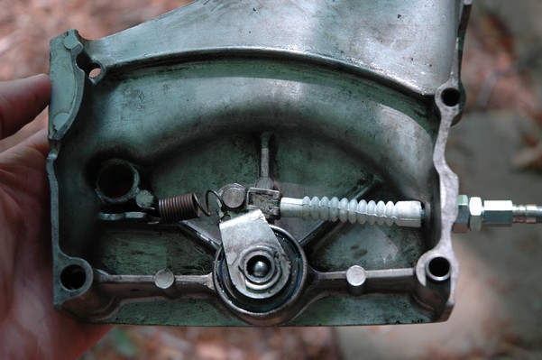
I figured I'd start up the motorcycle and ride it around the yard a little, mostly to try out the new fuel tank and to get some fresh fuel into the float bowls. It starts and runs fine, but as I found out it didn't have a functioning front or rear brake, and the clutch seemed to be intermittent. I've readjusted the brakes, and am hoping that will do for now. As for the clutch, I took off the side cover to take a look at the adjustment mechanism. I wasn't surprised to find that the grease was really old and flaky, but I was surprised to see daylight through the hole where the grease nipple is supposed to be. I cleaned and regreased the clutch pushrod and the adjustment pieces, and it does work much better now. The clutch drags some, but I think that is probably related to the sitting. Hopefully after some engine running it will free up some. The 175 had the same problem in its early days.
6-2008 Update: After 200 miles or so, the clutch was still dragging. This made it difficult to ride the motorcycle, and it was not possible to shift into neuteral when the engine was running. I've replaced the clutch, and found a lot of rust on the old plates that would probably have led to the dragging.


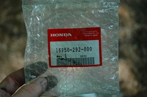
I also got a new clutch cable and some new brake shoes for the front brakes. I figure I'll need them sooner or later, though perhaps sooner. I'm still having trouble getting the neuteral indicator switch to work, since it looks like it took some damage in an earlier time. I re-primed the air cleaner boxes to try and keep the rust at bay. The last picture above shows the Honda part number for new kick starter and gearshift rubbers, while the last picture below shows the Honda part number for the new petcock.
The neuteral switch hasn't been working, so I tried to take a look at the contact. I couldn't figure out why there were two leads until I looked at the contact on the 175. The contact was actually a V shape, and the end was worn completely off. I've got a spare left over from the extra parts box for the 175.

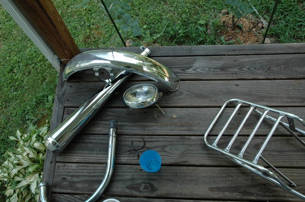
I had initially planned not to do much cosmetic work at this phase of the project, but I couldn't resist a little chrome polishing. On this round I worked on the front fender, left exhaust, headlight rim, and my makeshift luggage rack.

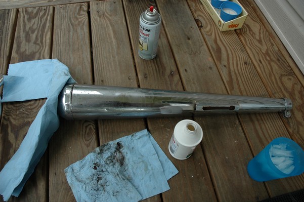


You can see a little bit of progress. I have found that the turtle wax polish works well, especially when teamed with something like a utility knife to scrape at the rust deposits.
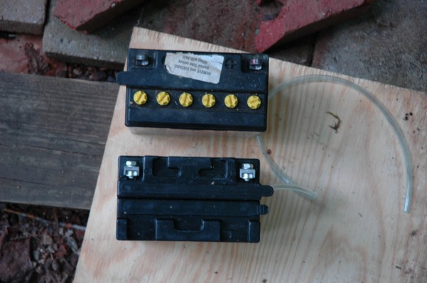
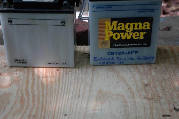
I do like to think that painting the battery box is a good idea, if for nothing else other than corrosion protection. Below you can see the result, along with the discrepancy between the battery that was in it from before (12N9-4B-1) and the correct battery (CB12A-AFP).
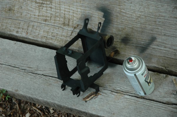

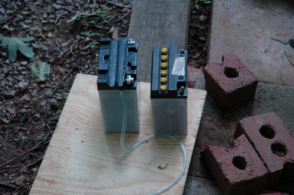
I guess that is one of the funny things about restorations- sometimes you can't trust things as they are when you start the work. You can see the height and width differences, and the height difference explains why there were wood scraps in the battery box from before to shore up the old battery to the correct height. I found a little contact cleaner to be especially handy in trying to troubleshoot all of the many electrical faults.


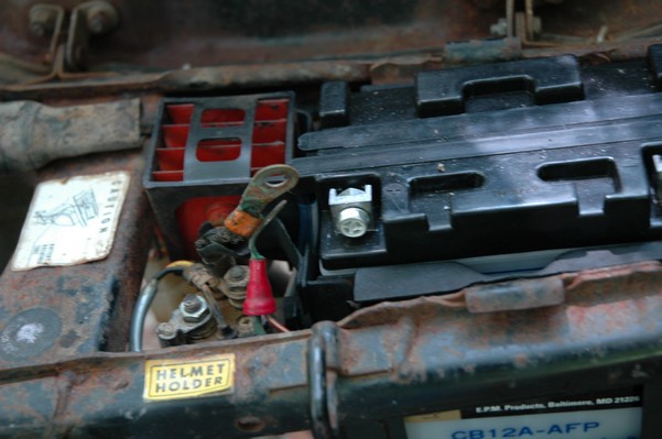
Below you can see the box loaded up and ready to go in. It supports the voltage regulator, selenium rectifier, starter solenoid, and a crossover tube from one air filter to the other. I wrapped the positive lead that goes to the starter solenoid with electrical tape since the original insulation is all but gone. Maybe in Phase 2 I'll address that with a little more professionalism.


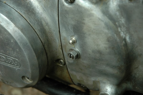
Here you can see the grease fitting going in. I used a small socket to support it while I tapped it in with a couple of light hammer blows. I found the new one in South Carolina thanks to ebay, all the while not realizing that I also had a spare one of these on my extra 175 engine parts. Which reminds me, I've got to do something with that big box of parts. Doesn't somebody out there need some gears or a crank for a CB175?

Can you see why I couldn't resist polishing the chrome? Check out the difference between the left and right exhaust pipes. It is just such an amazing result, and besides, it is sort of theraputic to sit in the shade and do something that requires few higher brain functions. Watch the progression below as the rear fender takes its place.


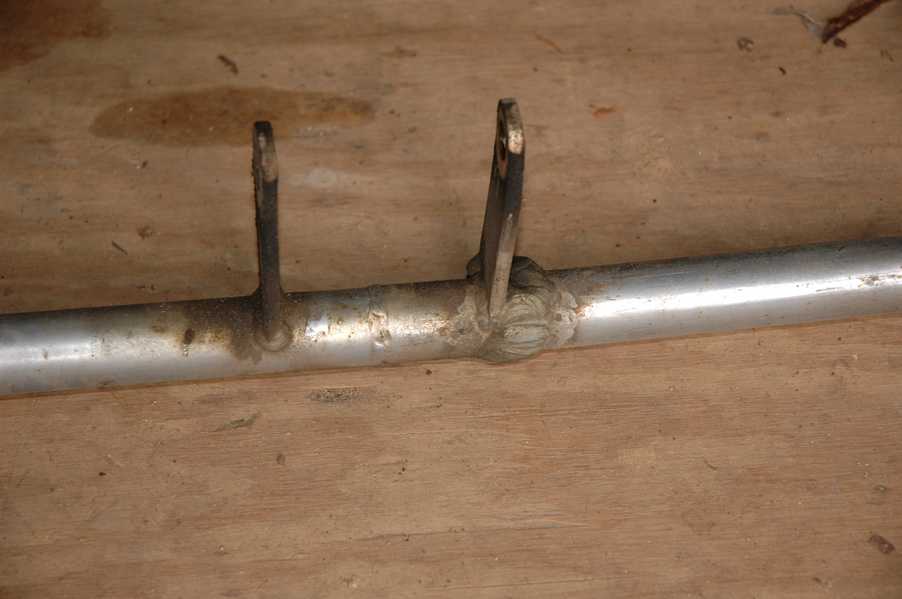
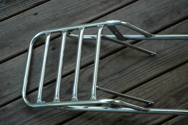
One of my complaints about the SL175 is that I don't have place to put stuff. I found this luggage rack on ebay listed for a CL175, and I paid about $40 for it, thinking that it would solve the problem. In fact, it didn't. The rear part of the frame on the CL differs enough from the SL to make it not even close. It does actually almost fit the 350 though, so below you can see a few modifications that I made to prepare it for final installation. The first three pictures show the delima. The second, third, and fourth pictures show how nicely an L-shaped bracket can solve the problem.


And now, through the miracle of television, you can see that bracket appear before your very eyes. Pay no attention to the tail light housing that also appeared while you were blinking. Note that the bracket uses two holes on the vertical member. The luggage rack only has one, so I will have to drill the other hole.


Check out CB350 Page 2 by clicking here.
| Home | Contact Me | Copyright © 2014 Jared Yates - All Rights Reserved |
|
Privacy Policy | |
| This page last modified 06/21/24 | |||||