Putting it all Back Together
Part 4 of the continuing saga of my 1970 Honda SL175As you saw from part 3, I took apart the engine to replace the gaskets and seals. Since they were original as far as I know, the bike left a puddle of oil everywhere I parked it. While this did have some benefits, including the ACCPP (automatic continuous corrosion protection program), POCP (progressive oil change program), and the HGNS (Hansel/Gretyl navigation system), it also had the obvious drawback of marking up the parking area. You can read all about the engine disassembly here.
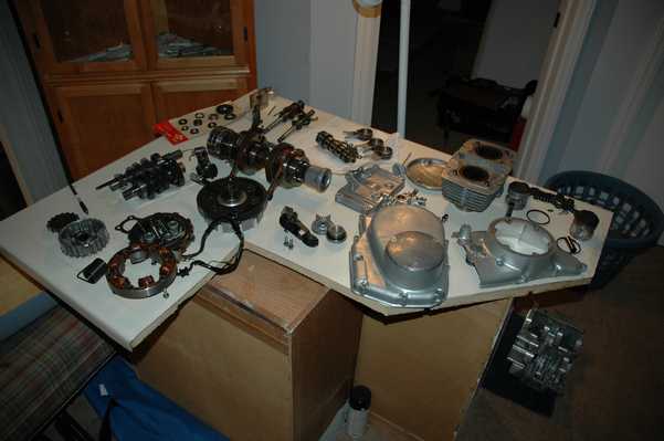
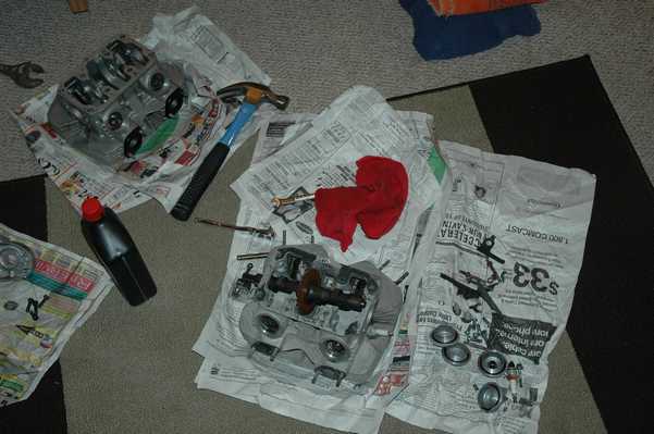
My first step was to clean the parts, lay them out, and see how many of them I screwed up while taking them apart. Luckily, there were few. I did find a few parts that broke themselves, including the cam chain tensioner and the kick start ratchet. I was able to find a bottom end from a CL on ebay for $30 with shipping, with hopes that I would be able to sell some of the parts that I didn't need. As a matter of fact, I still have quite a few left, so let me know if you need anything from the bottom end.
I was also glad that I was in the midst of a kitchen renovation, since I happened to have a free cabinet and chunk of counter top to use as a workspace.

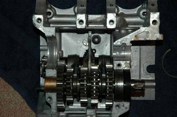
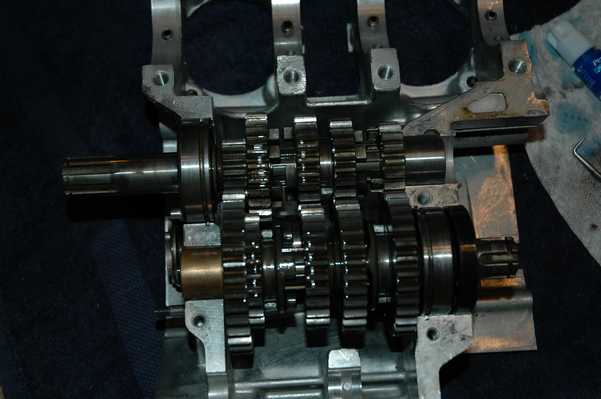
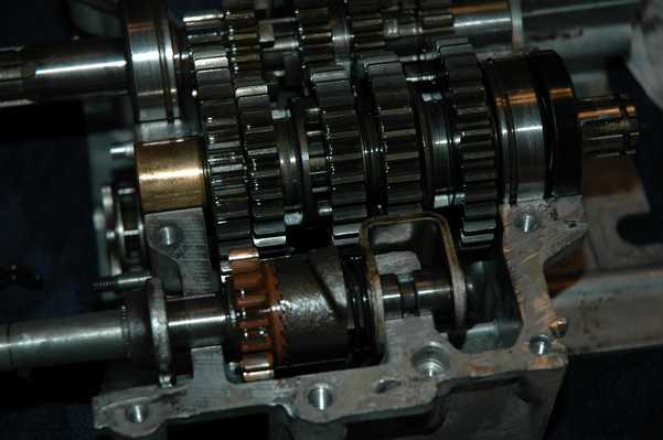
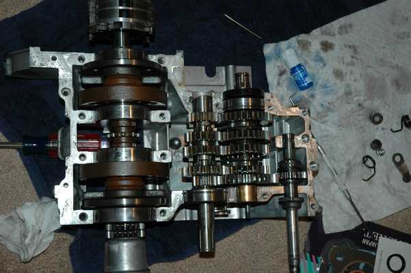
The engine went back together just about as the Haynes manual said it should. I did spend some time scratching my head and trying to figure out how the transmission worked. Everything took a better turn once I figured out that all three shifting forks didn't go on the same shaft. The third picture on the row above shows the drum/forks and the first half of the gears in place.
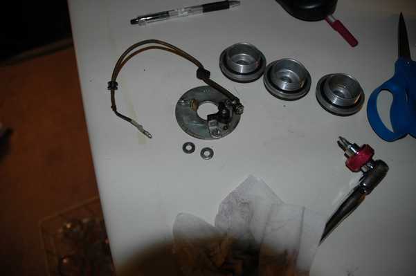
So now we come to the kick starter shaft. Since Honda made 3 motorcycles with the same engine, I figured that the CL bottom end that I found would have the parts that I needed. You can see in the first picture below that they are indeed different parts. Since the CB and the CL had electric starters and the SL was kick start only, I guess Honda decided that the SL needed a more profound system. The bad part is that my SL's ratchet mechanism was worn out, and so is everyone else's. If you look in the picture the top shaft is the SL, and you can see where the orange pinion meets the dark cast piece. The wear is obvious even in that picture, where the teeth have space between them even when they are engaged. There's nothing worse than stalling in traffic, kicking the kick starter to have it slip and not turn the engine, and having to push the bike out of the way while the lines of cars pass by. Then there is the process of trying to find a place to roll start it, etc. It just isn't good for image, though it does seem to be pretty good for cardiovascular health.
At any rate, look at the second and third pictures below to see the two different shafts in place. Since parts were not available for the SL shaft, I decided to try and use the CL shaft that I already had on hand. They both engage the same gear in the same place, they just have a different way of releasing once the engine starts. They looked like a close enough match to me, so I put in the CL shaft. Now that I have everything back together, I have to say that I can't tell any difference between the two. On a related note, my CL shaft was fairly worn where it meets the kick start lever, so I had to go through a different process to keep it from slipping outside the engine. More on that later.


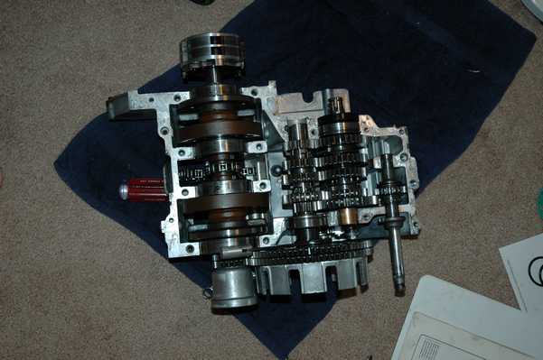
In this line you can see the remainder of the assembly for the top half of the case, along with the preparation for mating the top half. I used gasket sement from my local auto parts store. I should say too that during the reassembly, I sat next to the computer and found my pictures from disassembly to be extremely handy.


I started to go ahead and reassemble the top end, since I was planning to move and wanted to limit the number of loose parts. The head presented quite a few problems in my case. The first was the broken-off cam chain tensioner screw. Since it was broken off deep into the hole, I found that the extractor didn't work very well. It makes sense that the tapered extractor probably spread the remaining screw, further tightening it in the hole. That is the best explanation that I can figure for why I was able to break the extractor off in the screw, which in itself is quite a bit of trouble. Since it is made from some extremely hard steel, there is no hope for drilling the extractor out. Instead I decided to drill all around the tip of the remaining piece, in hopes of excavating it. That's when I started breaking drill bits in the hole, and that's when I decided to work on something else for a little while.


I was able to extract another broken screw from the top of the head with no trouble, and then I turned my attention to the exhaust. The exhaust shield was slightly damaged from a scuff with pavement in its last life, and slightly rusted from the time since then. I removed the screws and polished the shield, and thought about painting the exhaust pipes with some high-temp black paint. In the end I chickened out about that step, worried that the paint wouldn't stick and would make things look worse.
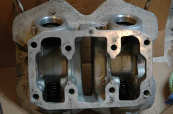


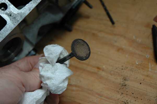
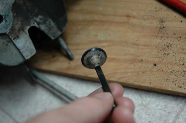
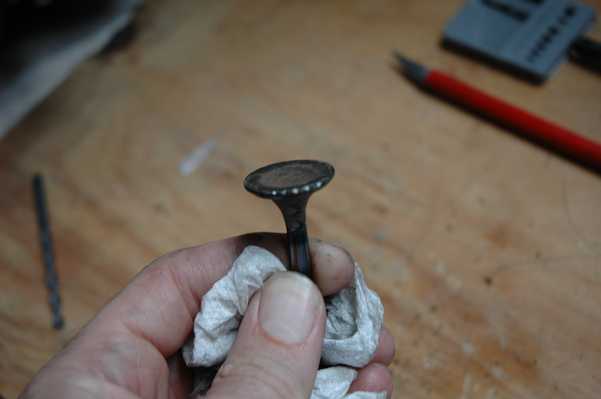
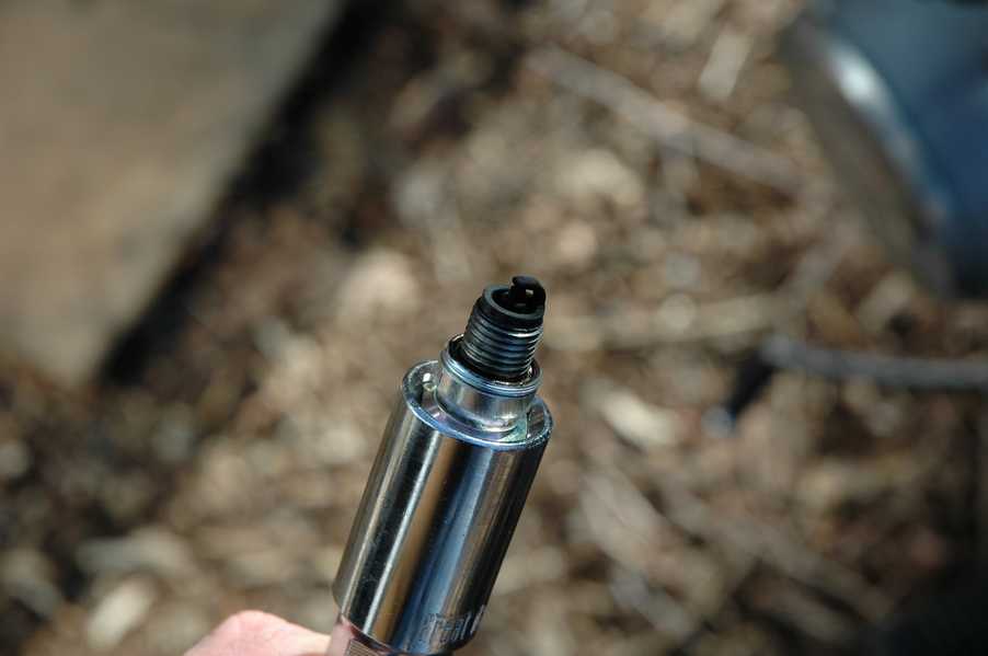
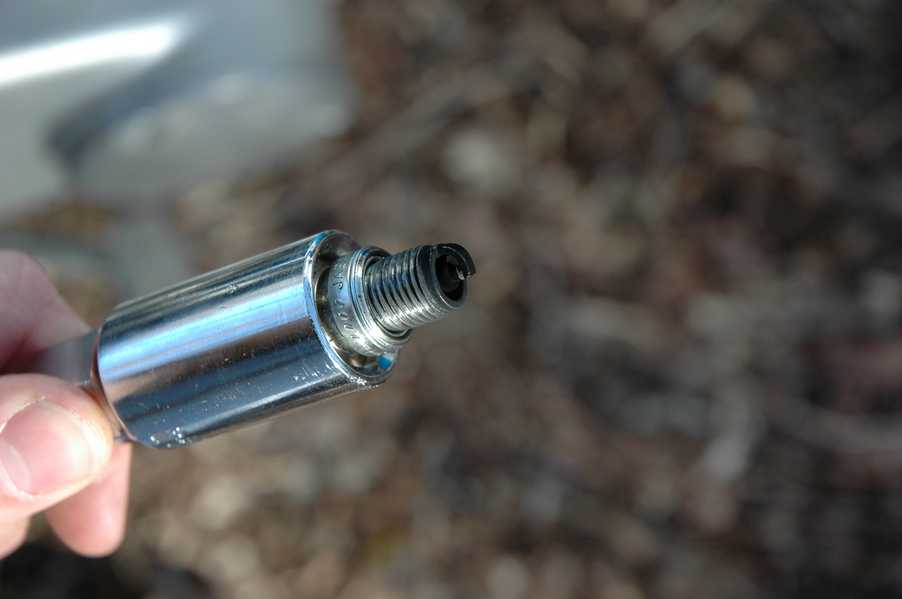
Speaking of worse, that is about when I found the exhaust valve problem. With the cam shaft removed there is no reason for the valve to be open, but I could look down the exhaust outlet and see light coming through. This was an indication that the exhaust valve was stuck open. There was plenty of carbon buildup around the valve seat, but it turned out that his was more of a result of the true problem, which was a bent valve. I guess I did this during the spark plug thread repair, as indicated by the shiny marks on the valve. You can see that there are also was a lot of carbon buildup on the other valves.


You can also see the thread repair insert.


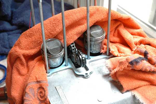
Getting the cam chain in the right place is easy when the cylinder block isn't in place, but it gets harder as the stack gets taller. I took the studs off for easier working on the engine, so it was time to put them back on. It was also fairly easy to get the pistons and rings back into the cylinder, thanks to a little oil and some patience.
April 2008 Update: I did not replace the camchain during this step, and that was a mistake. You can read about that in subsequent parts of the story.


When I was finished taking things apart, I found a little ball rolling around. Since I had no idea where it came from, I took some time to check out the microfiche. It turns out that it goes on the left side of the clutch pushrod. You can see the ball in the last picture above.


With all of the problems with the cylinder head, it was starting to make sense to find a replacement. I found one on ebay with four valves and springs in place for less than $30 with shipping, which solved all of my problems. Just like that, I had new cam chain screw threads, new valves, new spark plug threads, and four extra valve caps. The worst part is that I spent $50 on the spark plug thread repair kit for the old head!


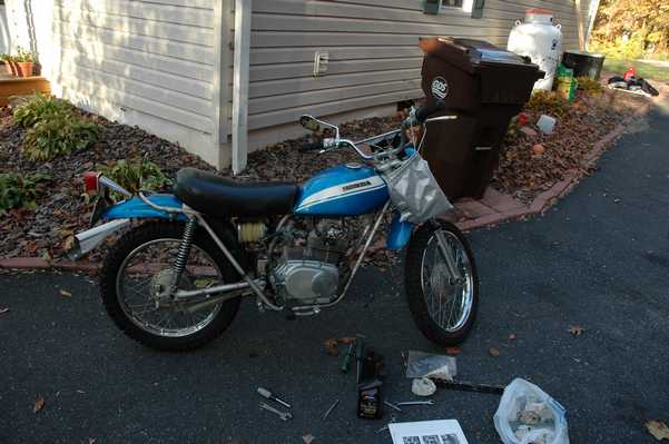

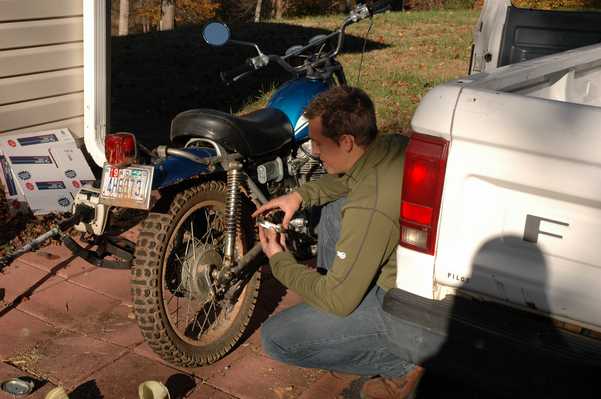
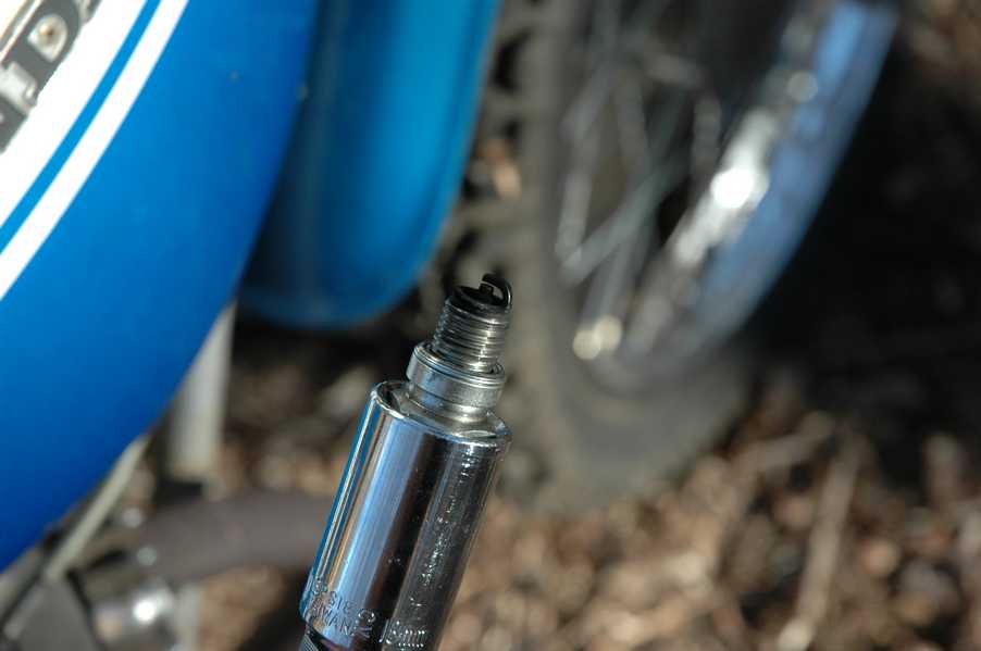
The final touches included a new chain, a new clutch cable, and a new speedometer cable. I found the cables as NOS on ebay and found the aftermarket chain there too. In the picture of the front wheel you can see the speedometer cable and the front brake cable. Since the bottom cable (brake cable) is so much older, the colors are a little different.


So the two important questions are... how many parts did I have left over? and did the engine run afterwards?
Since I replaced several parts, I actually have quite a few left over. Hopefully they are all replaced by newer parts inside the engine.
As for the second part, I'll have to say well, sort of. At first the engine didn't really idle well or run well at high speed. I wanted to replace the original carb gaskets, since they were seeping fuel. I found a pair of carb kits on ebay, and while I was cleaning the carbs in preparation for re-installation, I went ahead and replaced the jets and needles from the kits. When it didn't run right, my first reaction was to take out the new jets and needles and put the old stuff back in. When I took off the left float bowl and gave the remaining fuel a toss, I heard a little clinking noise that turned out to be the main jet saying goodbye as it went sailing across the driveway. It turns out that it had unscrewed itself and fallen into the bowl, leaving the high speed circuit free to suck as much fuel as it could at high engine speeds. Given the circumstances, it wasn't really running that bad at all. Once I put the old needles and old jets back in the high end cleaned up and started running perfectly. This was quite a relief, since one of may main reasons for all of that engine work was to improve the weak compression on the right cylinder. But, the idle was still not right.
It turns out that since the SL has different intake and exhaust systems, the pilot jets are a different size. So, if you are going to buy carb kits or jets, be sure that you get #38 pilot jets instead of #35s. It turns out that on mine there was one #35 and one #38, so maybe that's why it didn't run as well at idle. I have some new jets on order that should be in soon, thanks to Honda for still being able to get them. Most of the other parts are discontinued.
April 2008 Update: This is wrong... don't believe it. The microfiches that I've seen say that the CB and CL also call for the 38 jet, so I don't know why my kit included a 35.
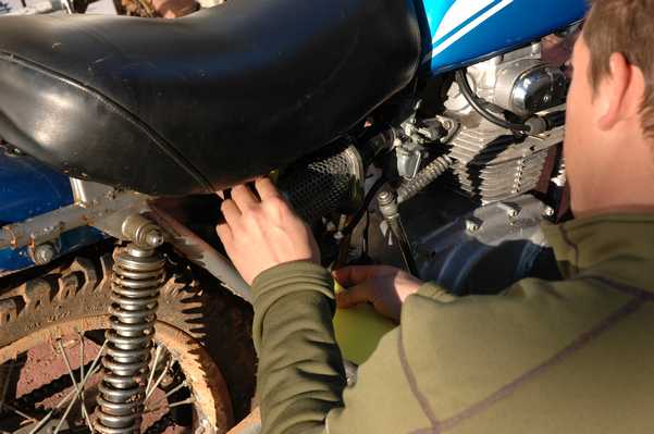
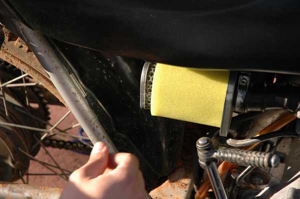
In asking around about what could be causing my problem I figured it might be time to replace the air filters. The local places didn't have any bulk foam to cut filters from, and I didn't want to buy the $25 that the guy is selling on ebay. Instead on Scott's whim we decided to try NAPA. With great luck, we found a pre-filter for a lawn mower. The picture quality isn't great, if you could see well enough it says "Replaces: Briggs and Stratton 270728, 271794 John Deere M96098 Fits 7-02210 Air Filter." The NAPA Bar code says R789337, and the bar code says 7 07390 44114 6 and there are also 060603 7499-E2 written on there somewhere. The best part is that two of the filters from NAPA will give you enough foam to make three motorcycle filters, and you should be able to get them both for about $4. As Scott demonstrates, you do have do a little bit of stitching. The only other catch is that you have to center the foam over the holes on the can, as you can see below. When centered, the foam does provide coverage of the intake air, but if the foam was about 1/2" longer, it would fit perfectly for length. But, for $4, it will do fine for me.
April 2008 Update: Read on to find out about the Uni filter. Also, if you use this method, don't forget to oil the foam. I've since learned that on an air filter like this, the oil actually catches dirt, and the foam is just there to hold the oil in place. A dry foam filter does little to stop dirt.


Well, I got the new #38 jets and put them in. That made things a whole lot better, but the idling problem was still there. I've been chasing down lots of different possible sources of the problem, but haven't found it yet. On person I spoke with suggested that it may be a valve timing issue, and that perhaps I was a tooth off on the cam chain. I started to suspect this too, so I did some investigating. First, I took off the carbs and put some gasket goo on either side of the paper gasket that goes between the phenolic disk and engine block. I figured this was about the only place that there could be an air leak between the carbs and the cylinders. This didn't make much of a change.
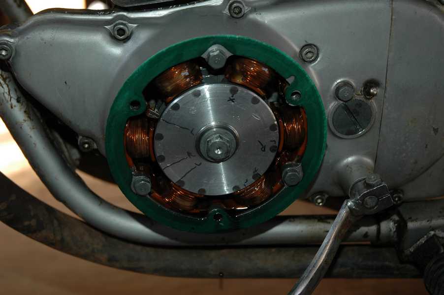
Next I took off the rocker arm cover to take a look at the cam chain. I also made some marks on the generator rotor so that I could try and get an idea of when each of the valves was operating. For the most part they seem to be operating just as I would expect them to. In this process I also figured out that a single tooth on the cam chain equates to about 20 degrees on the rotor, so there isn't much of a chance that I'm off a tooth. It could still be a valve timing issue, but if so it isn't because the chain is off a tooth. While I was in there I also checked the valve clearance again, and it was still where it was supposed to be.


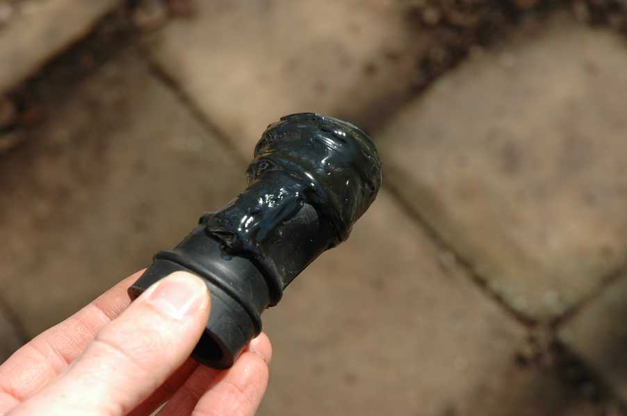
After I put everything back together the idle problem was still the same. I took some pictures of the plugs at various engine speeds, and they seem to look a little bit rich. I tried running the engine on one cylinder with the other spark plug out, and found that the left side is definitely a lot worse off than the right. Since this was the side with the bad rubber tube, I decided to take some time off and repair it more thouroghly. I haven't been able to find one for sale anywhere, and there aren't any reproductions available yet.


Meanwhile I took a little time to work on the 1972 CB 350.

I didn't have any luck finding a rubber intake tube, so I tried to do a better job of repairing the old one. Here are the results:


I posted a question on thumpertalk.com to try and get some hints about what could be causing my idle problem. After re-checking all of the popular problems, someone pointed out that the slides could be swapped between the left and right carbs. This was a surprise to me, since I always treated them like they were the same part. It turns out that they aren't, and it also turns out that I had them on the wrong sides. You can see the differences in the pictures below. The first picture shows the angled cut on the bottom of the slide. This angled side faces the inoming air when the slides are in correctly. The second picture shows the two slides beside each other, with the throttle stop slot on the right in both cases. In that configuration one has the angled cut on the top of the picture, while the other one is on the bottom in the picture. The last picture shows that they have different numbers stamped on the bottom- 155 and 156.


After getting these put back in the right place, it started up and ran very well. I followed the pilot-screw adjustment procedure from the Haynes book and it ran even better.

After the adjustments I wanted to go inside the house to get my riding gear, so I left the bike outside idling at 1500RPM. After about 5 minutes inside, I came out to find it idling away, right where I had left it. That almost made it all worth the trouble! Now it's back to normal, just in time for the spring riding weather. Now, if only it had another 20 horsepower...
Check out the next update here!