SL175, Part 5
I've been tinkering with the SL175 for two years now, and I just recently rode through 1000 miles. That may not sound like much, but considering that most of those two years involved some stage of disassembly, it isn't so bad.My dad was in town in May with his Deuce and we went for a ride to the Linville Gorge and back. It was over 150 miles all together, and he was kind enough to slow down on the straight stretches so that I could keep up. Here are some pictures of the two bikes together.
I got an email from someone who told me that his kickstarter was stripped. I never did hear back to see if he was talking about the ratchet inside of the engine or just where the lever is, but mine was stripped on the outside. So if you find yourself in a similar situation, here is one way to fix a stripped kickstart or gearshift shaft.
You will need to round up some steel music wire, a good drill bit of the same size, and some JB Weld. Be sure to use good steel wire, and not nails or other softer metal. I started with nails, but after a few kicks they turned into splinters. I found the steel wire at a hobby shop in a variety of sizes for less than $1 for a 36" length. The size I used is around 3/32."
Step one is to mount the lever where you want it to be. Be sure it is in the right place! Next, drill a series of holes around the joint between the two. The idea is to split the hole so that half of it goes into the shaft and half goes into the lever. Take your time and don't break the bits!
I used a dremel to cut off four lengths of wire. I would suggest that you don't try to use side cutters, partly because they will probably break, and partly because you will end up with a sharp end that you will have to file.
Next I put a little JB weld on the pins and drove them into the holes with a few light taps of a hammer.
The finished product has to be a flush finish or you will end up making your boots look like this:
Here it is on the way to a memorial day weekend of fun:
Scott and I rode all over southwestern NC and northwestern SC for about 250 miles in one day. I only had to stop for oil once... I think it is still leaking somewhere near the tachometer drive. The other issue is the fork seals- they have leaked since day 1, so I'm looking for some replacements from a different source.
3-2008
It's been quite a while since I've made any updates, and there are quite a few to make.
Back when I refreshed the engine, I missed at least two things that I should have fixed the first time. The first is that there is a very small oil seal on the tach drive that I didn't replace. This wasn't too hard to fix, but I did have to track down the new seal. The other problem was that I didn't replace the cam chain. What I didn't know before is that as the cam chain stretches, the valve timing degrades. Even though I only had 5000 miles on the old one, it did have some problems with the tensioner, so I should have replaced it anyway. These two repairs are sort of related, since I did them both after taking the engine out one day. The second, third, and fourth pictures compare the new and old cam chains. The new one is on the left. You can see a total length difference of around 3/16" or so. The last picture shows both chains bent to their maximum arc. There is quite a difference between the left and right.
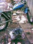
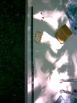

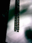
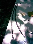
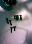
While I had the cam ends off I replaced the stock screws with allen head ones. The stock phillips head screws were stripped, and I didn't see any need to replace them with the same type again. The second picture below shows the honda part number for the seal that I replaced, along with the part number for a seal kit to go in a CB350 engine.
The crankcase breather tube that I had wasn't looking so hot after 35 years, so I figured I'd try a vinyl replacement. It is cheap, so if it doesn't hold up well I haven't lost much. It is 1/2" OD and 3/8" ID.
Thanks to some help from Bob, I found a great skid plate on ebay. I haven't installed it yet, but I have been cleaning it up and getting ready to repaint it.
I'm going to experiment with some electrolytic rust removal, and hopefully I'll have a web page about that soon. I think the skid plate is a great candidate, as are the exhaust pipes.
On a recent ride I lost the pin that holds the seat on. I know about where it fell out, but after a brief search, I couldn't find it. As a replacement I installed two separate 6mm bolts with nylon lock nuts. I think these will be less likely to fail, partly because of the lock nuts, and partly because of the redundancy of the two separate bolts.
Another little nagging problem has been my fuel leaks. Fuel was leaking past the petcock in the off position, and furthermore it was leaking from the float bowls. These leaks were very slow, and would only be obvious as a little discoloration after a week or two. I had rebuilt the petcock not too long ago, and since that didn't seem to stop the leak, I ordered a new one from ebay. The one that I ordered was a replica from taiwan, and it was terrible. The quality was not as good as the Keihin, which was to be expected, and the rubber parts were all rock hard. I tried polishing my original lever, in hopes that it would seal better against the 4-hole rubber washer. This turned out to be more of a problem than a fix, since I ended up reducing the thickness of the lever. In the end, I took the lever out of the sandcast part, and put it into my stock petcock. Since the sandcast lever was thicker (as you can see below), it seals tighter against the rubber. This has stopped the leak for now, so I'll stick with it.
Another frequent problem that I have had has been with the front brake switch. They are very fragile and easy to break if you are not careful while removing the lever. The other problem is that the housing that covers the wires on the stock switch gets brittle over time. I don't have any gray colored housing to use with the wires, so I just wrapped them with electrical tape and spray painted them. How is that for redneck engineering?
I was still having trouble with getting the bike to run consistently, so I figured the problem must be the rubber tube that has been giving me trouble for the past couple of years. It goes from the stock air cleaner to the carb, and as you may recall, my left tube was in pretty bad shape. The right one was free of cracks, but it was pretty hard. I was out riding this fall and some of my repair compound broke free of the left tube and plugged the carb pilot air passage. I'm sure I looked pretty silly riding home with 3000RPM at the stoplights, but since the engine wouldn't idle any lower than that, it was my only option for getting home. I have not been able to find the tubes anywhere, so I went out a limb and installed some pod air filters. They are the UNI 6025, which means that they are 6 inches long and have an opening of 1.25 inches. That opening is a little bit big, but they are designed to allow for some size variation and seem to seal just fine.
When I put the filters on I was hoping that it would run great right from the start, but that was wishful thinking. It wasn't idling well, so I started checking all sorts of things. In the end I found that I had fuel in my solder-repaired carb float. I've definitely decided that this is not an acceptable way to repair floats. Once I replaced the float it got a lot better, but was still running rich and inconsistently. My uncle suggested that maybe I had over-oiled the filters, so I cleaned them and re-oiled them with just a little bit of oil. I put some comments about the idle problems here and started working on fixing them.
I get messages every week or so from people who find my website. One was from an original owner of an SL175, and he told me that his has never really idled very well either. This is a bit reassuring, leading me to believe that perhaps my standards are just too high. I never did find the jets, but it seems to be running better on the others. I was having some trouble getting consistent plugs on the two cylinders. One was always rich and the other was looking about right.
When my new float came in I did some research about setting the float height. It is possible to measure from either the gasket face on the carb body or from the bottom of the case. While there is a little bit of debate about which one is correct, I'm convinced that it is the bottom of the carburetor case. Once I got it back together it was running well enough to ride on the street.
The OEM wire harness jacket had gotten old and hard with age, so it was causing the wires in the bundle to flex in the same spot each time I turned the handlebars. To help keep the stresses more even, I removed the original black plastic and replaced it with a softer spiral wrap. Now the wires bend along a stretch of several inches, so hopefully they will last longer. Below you can see the area that I'm talking about.
On a recent trip to Oshkosh, Wisconsin for the annual EAA Airventure, I saw all sorts of old motorcycles. In fact, here is a CL100, which is closely related to the SL. The other bike is the SL70, and both are in great shape. I wished that I had mine there so that we could take a "family picture."
Here is the skid plate again, this time after some electrolytic rust removal. I thought it turned out very well, and the OEM paint softened very nicely. I painted the steel plate and the aluminum mounting brackets with a high temp flat black paint, since they are so close to the exhaust pipes.
Speaking of exhaust pipes, they were next up for restoration. They were very rusty, and I was concerned about their longevity. The first picture below is "before." I used electrolysis to remove the rust, and then some light sanding to help take off the paint that didn't fall off. The last two pictures are just after cleaning, and just prior to paint.
The first picture below shows the extent of the pitting on the part of the pipes closest to the engine. The next two show the paint after the fact. I used Sperex VHT, which is supposed to hold up to 1200 degrees C or so.
Here are some pictures of us getting ready to ride. We were going to go to Arizona to do some riding, so we switched out and let Tabitha ride the heavier CB for practice. You can also see her new riding jacket complete with CE Approved armor. Hers is mesh, where as mine is solid with zipper vents.
Now skip ahead to the fall of 2008 for several overdue updates. On the last time that Tabitha and I were riding, she was on the 175 and I was on the 350. We were on a 2-lane road far away from town. We missed the turnoff that we were looking for, so I stopped in a parking lot. She went up to the next left turn to do the same, but just as she was starting to turn, the impatient car driver behind her decided to cross the double yellow line to pass, knocking poor Tabitha over. I was watching all of this happen from my vantage point, and it looked at first like the car driver wasn't going to stop. I expeditiously started to head in that direction, but by the time I was there the car driver had indeed stopped and there were a few people on hand to help. Tabitha was OK other than being slightly bruised and of course very shaken. The good news was that both she and the car were going pretty slow at the time of the impact, and that Tabitha was well dressed with her riding jacket. The bike landed on the left side, and the results were a dented and scratched front fender, a bent gear shift, scratches to the muffler heat shield, a destroyed left mirror, and some damage to the left grip. After the highway patrol left, we were able to take one of the mirrors off of the 350 and get the 175 road worthy again. I rode it around to make sure that everything operated well, and we continued on to our destination. You can see some of the collision damage below.
There is no doubt that we could have probably prevented the accident with turn signals. I had not installed them simply because NC law does not require them, and since it wasn't equipped with them when new. As part of the repair, I decided to add them to help make riding safer for the future. The first step was to replace the left hand switch with one that has both the horn and turn signals, instead of just the horn. The switch that I had came from my CB350 spare parts box. The mirror mounts to the switch, instead of to a separate perch like in the stock 175 setup. I had to cut the damaged grip off to remove the stock perch, so now was a good time to make the change.
Before I removed the old switch, I attached a leader to the wire so that I could fish the new wires through the handlebar. The new switch only has four leads. The green is for the horn. The gray, orange, and blue are turn signal related. The orange lead is for the left turn signal, and the blue is for the right. In the Hondas of this vintage, the black wire is the positive lead after the ignition switch. Electricity flows from the positive lead on the battery to the ignition switch via a red wire, then when the switch is selected to the red dot, the black wires become connected to the red lead. In the case of the turn signals, the current flows from the black lead to the turn signal flasher, then upon exiting the flasher, the wire turns gray. The gray wire goes to the handlebar switch. If you select left turn, the switch connects the gray to the orange, and the current continues to flow through the orange wires to the turn signal bulbs, then to the metal frame, which is connected to the negative lead on the battery. In the case of a right turn, the same process happens, just to the blue wire instead of the orange one. In the case of the SL, the stock wire harness includes the wiring for the turn signals and flasher relay, so I was able to add the signals without having to run all of the wires.
I also needed some stems for the turn signals, and I was quite pleased to find brand new ones for sale at Dennis Kirk. The threads on the turn signal stem are the same as the threads on the chrome plated bolts that hold the headlight bucket onto the chrome fork ears. This means that the turn signals will replace those bolts and serve double duty of holding the headlight in place. In the end, I decided not to use my beautiful new stems, but rather, to use an old and pitted set. I cleaned them up as you can see with the before and after view below, and then painted the exposed parts with a black epoxy paint.
For the rear stems I used the brackets off of a CB350. Back before I purchased a large collection of parts and spares, I really was looking for some of these little brackets. Now I have a few extras, so I was glad to have them for the SL. I used electrolysis to remove the rust and soften the paint, then finished the job with the wire wheel. I also painted them black with the epoxy paint. I mounted them under the washers and nuts that hold on the rear shocks.
My next task was to get the fender back into shape. I was able to bend it back pretty close to its original shape, then I removed the old paint. As you can remember, there were a few layers. The first was the OEM, then there was the old repaint, then there was my repaint. In some of the pictures below you can see all of the layers, including the red OEM primer.
While I had the front end apart, I decided to go ahead and redo the forks. I had replaced the fork seals before, but found them to still leak. I think this leakage was due mostly to some damage and pitting that allowed the oil to sneak past the seals. You can see these marks in the second picture below. I read about this phenomenon in my favorite motorcycle magazine, Classic Motorcycle Mechanics. Ever since I learned about this magazine from Craig at work, I've been a huge fan. It is pretty expensive to have it imported, but the information makes it worth every penny. While I had the fork ears off I cleaned and polished them a little.
The first picture below is my improvised method of separating the fork parts. Just like last time (see part 1), it wasn't easy. In the second picture you can see how I had to attach the oak piece to the ceiling in order to get enough mechanical advantage to separate the parts. The last picture shows my new seals.
The technique that I learned from the magazine is to clean up the fork legs and file off any burrs, then to coat the effected area with JB Weld. The proper way to fix the fork legs is to turn them down on a lathe, then re-chrome them to bring them back up to size. The cheap way however, is the JB Weld. After it hardens, you file almost all of it off, theoretically leaving just enough to bring the pit or scratch just up to the level of the surrounding surface. I installed a set of Daystar Fork boots to help keep the fork legs clean and safe. It is the Daystar number 58 boot. It is a pretty good match, though the outer diameter is a little bit too large. I also had to shorten them a bit. My goal was to have the boots in a relaxed state with the weight of the empty motorcycle, so the boots had to be a little bit extended when the front wheel was off of the ground. You can see the shortening process below.
Here is the flasher I decided to use. Back in the 1970s, Honda used a very basic thermal flasher whose flash rate varied with the amount of current demanded. This meant that if one bulb was out, the other would probably not flash at all. Also, if the battery was weak, at low engine RPMs the signals would not flash. Since modern electronics are as they are, Bussmann has a nice little flasher that will do a better job. Its flash rate is independent of current demand, and best of all, it costs about $2 at your favorite store. The flasher I used is Bussmann item 552, and for me it's a no-brainer replacement. As you can see below, I just cut the OEM honda bullet connectors off of the gray and black leads that terminate under the seat. I soldered on some connectors that would fit right on to the flasher and plugged it in. I don't think it matters which lead you put on the flasher, it seems to work either way.
Since I switched to the UNI Pod filters, the old mounting holes for the OEM air cleaners were available to support the wire ties for the flasher. If you are doing the same and are still using the OEM filters, I'm sure you can find an easy place to attach the flasher in some other way.
I replaced both grips, since replacing just one didn't seem very wise. Since the right grip was not damaged by the accident, I didn't want to cut it off of the plastic sleeve. Instead I consulted my pile of CB350 parts and borrowed one from the stash. You can see that the right grip has a larger inner diameter.
I decided to try the two-layer paint process that I had heard about from one of my website visitors on the fender. The paints are sold by most auto parts places under the "Duplicolor Metalcast" name. The first layer is a silver, and the second is a transparent blue. This is similar to the process that Honda used on the OEM paint. I put on the first layer of silver, then put the blue directly over that. The end result wasn't very good. I sanded off most of the blue, then re-coated the silver. On the next run I sanded the silver before the first coat of blue. One thing that I didn't expect about this process is that the surface has to be perfectly smooth. Since mine wasn't, I had some visible blemishes in the final product. It's not show quality, but it is very functional. I found the best result was with wet sanding everything but the last layer of either color.
My last task was to trim the side covers so that I could start using them again. Since the UNI filters are larger than the OEM tubes, they needed more relief from the side covers. I was reluctant to alter the covers, since they were in a fairly good stock condition. In the end I was able to cut out a small crack on one of them, so that made me feel better. You can see the before and after in the first picture. The rest are just glamour shots that I took after I washed it. Hopefully the days of leaking lots of oil are coming to an end.
Click here to read part 6!